3D laser scanner
An implementation of a line laser scanner
Introduction
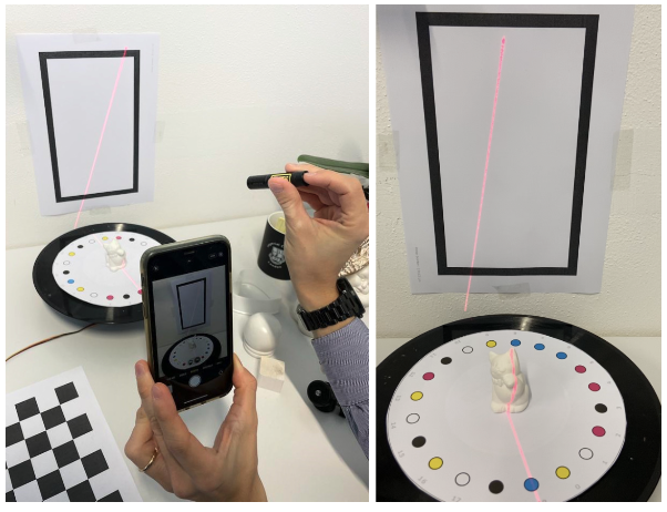
This project consists in a traditional geometric line laser scanner, where by leveraging the geometric properties of a structured light pattern (in this case a 3D plane), it is possible to infer the object shape based on how the projected pattern adapts to the object surface. So, given an input video like the one in this figure:

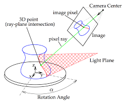
our goal is to output the object surface point cloud, i.e. a point set \(P: p = (x, y, z)\). The following figure shows a scheme of the setting:

Methodology (~draft)
The first step is the estimation of camera intrinsic parameters and distortion coefficients by calibrating the camera using a traditional chessboard pattern (9x6), accordingly to OpenCV official documentation. As known, the process is similar to pose estimation and relies on projection error minimization. With camera intrinsic parameters, it is possible to undistort the image and to compose the complete camera matrix once the pose is estimated.
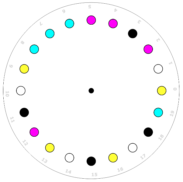
\[\begin{equation} \label{camera-matrix} K \left[ R \vert t \right] = \begin{bmatrix} f_x & 0 & c_x \\\ 0 & f_y & c_y \\\ 0 & 0 & 1 \end{bmatrix} \begin{bmatrix} r_{11} & r_{12} & r_{13} & t_{1} \\\ r_{21} & r_{22} & r_{23} & t_{2} \\\ r_{31} & r_{32} & r_{33} & t_{3} \end{bmatrix} \end{equation}\]Two custom fiducial markers are present in the scene, the first one a rotating plate with a color-string necklace and the second one a rectangle. Leading to a total of three reference systems, i.e. the camera, the plate and the back-plane.
For each frame, it is possible to extract the 3D coordinates of the points belonging to the object surface hit by the laser plane since they are identified as the intersection of the 3D laser plane with the rays that starting from the camera optic center pass through the pixels in the image plane containing laser points. As known, a 2D plane equation in the 3D space can be derived from 3 points belonging to the plane itself. Two points are extracted from the back marker (express in the rotating plate reference system), while the third from a cropped region of the rotating plate.
Using traditional computer vision techniques, like thresholding, morphological transformations and contour finding, the markers features are extracted and the camera pose is computed as Perspective-n-Points. To solve the point correspondence of the rotating plate, the problem has been cast to a string alignment problem by associating each color to a string character and computing the offset using a voting system.

Once the camera pose is computed for both markers, it is possible to map points to each reference frame using camera homogeneous coordinates and projective geometry as in equation \eqref{camera-matrix}
Results
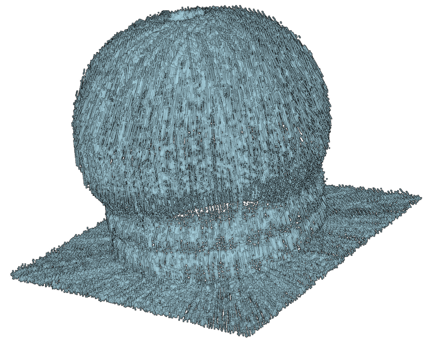
In this section, one of the reconstructed object is shown, together with the result of Delaunay mesh triangulation from PyVista:

